THE PHASE DOPPLER PARTICLE ANALYZER (PDPA)
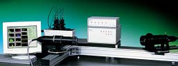
Phase Doppler measurements allow for the sizing of spherical particles. Along with size information, the velocity of the particle is also obtained, so in this sense the phase Doppler technique is an extension of LDV. The size of particles that can be measured is limited on the small end by the amount of light that is scattered by very small particles (which depends on particle size, laser power, and light collecting optics), and is limited on the large end by the Gaussian nature of the laser beams a nd the far field condition. Typical limits for common configurations might be 1 or 2 mm on the lower end and 500 mm to 1 mm on the upper end. The images of our PDPA which is manufactured by TSI is provided below.
The Phase Doppler Method is based upon the principles of light scattering interferometry. Measurements are made at a small, non-intrusive optical probe volume defined by the intersection of two laser beams. The intersection of the two beams creates a fringe pattern within the probe volume. As a particle passes through the probe volume, it scatters light from the beams and projects the fringe pattern. A receiving lens strategically located at an off-axis collection angle projects a portion of this fringe pattern onto several detectors.
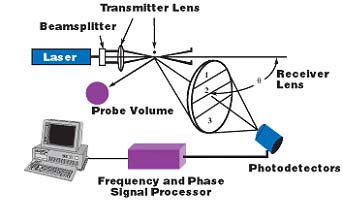
Each detector produces a Doppler burst signal with a frequency proportional to the particle velocity. The phase shift between the Doppler burst signals from two different detectors is proportional to the size of the spherical particles.
The Phase Doppler method requires no calibration because the particle size and velocity are dependent only on the laser wavelength and optical configuration. PDPA measurements are not based upon the scattered light intensity and, consequently, are not subject to errors from beam attenuation or deflection which occur in dense particle and combustion environments. The optical transmitter and receiver may be traversed together to move the location of the optical probe for spatial mapping of the flow field and of the particle size distributions.
PLANAR LASER INDUCED FLUORESCENCE (PLIF) SYSTEM
We have a Dantec Dynamics’ planar-LIF system for concentration and temperature measurements. This system is designed to handle whole-field measurement tasks with great simplicity and flexibility. The system fully supports synchronisation with velocity measurements (by PIV), allowing advanced investigations of heat and mass transfer processes. In addition to FlowManager’s powerful capabilities for image acquisition and visualisation, the planar-LIF software enables the user to effortlessly process fluorescence images and extract statistics, Reynolds fluxes and other information from the images for a better understanding of the process investigated.
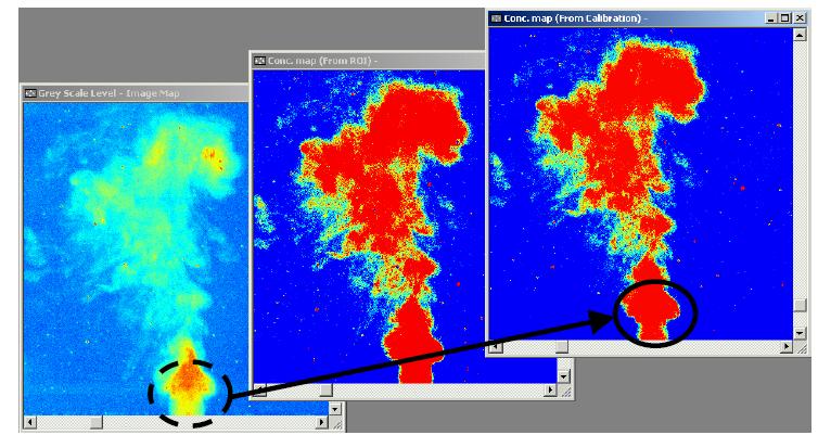
Image acquisition and analysis system for imaging gaseous flows by planar Laser-Induced Fluorescence methodology:
• Visualisation of the dispersion of pollutants, mixing etc.
• Concentration measurements of isothermal and quasiisothermal gaseous flows
• Temperature measurements of uniformly seeded gaseous systems
• Synchronised velocity/concentration and velocity/temperature measurements by PIV/planar-LIF methodology
Our planar-LIF system includes:
• A complete laser illumination system:
– High-power Nd:YAG laser with UV option (and residual green light for additional PIV measurements)
– UV light-sheet formation optics with optional light guiding arm for safe light delivery
• Dedicated imaging system:
– Dantec Dynamics’ FlowMap System Hub
– Highly light sensitive camera and optics components
– Optical filter directly mounted on a ring to fit any camera and optics system
• Dedicated planar-LIF software features including:
– Automated planar-LIF calibration and image processing methods for concentration and temperature
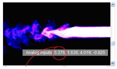
– Built-in laser energy pulse correction
– Mathematical routines for scalar map analysis
– Statistical tools for scalar map analysis
– Re-sampling technique based on vector maps for image adjustment with integrated PIV/planar-LIF systems
– Re-sampling technique based on calibration plate
– Simple methods for calculating Reynolds fluxes
• Further dedicated image-processing software add-ons:
– The Image Processing Library (IPL) software
– The MatLab® Link
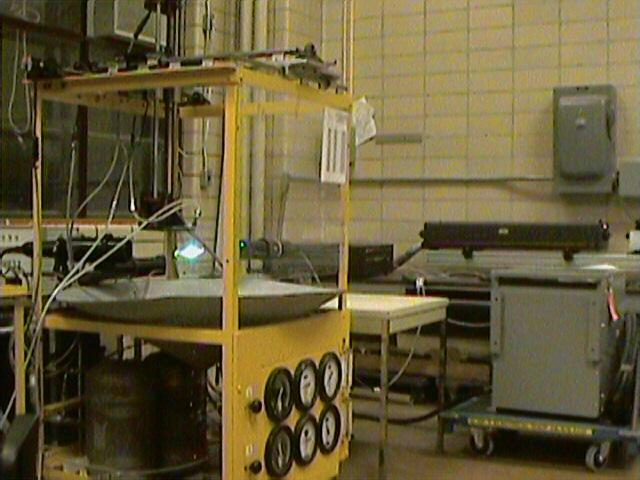
SPRAY BOOTH
MUSSL’s spray testing facility is shown below. This facility consists of a three dimensional traverse system, a spray booth equipped with a flow system. For the air flow, two different compressors are available. One compressor can continuously provide up to 90 psi air. For high pressure and high flow rates, a separate compressor (model HS781001AJ) is available.
YAG LASER
The TDL90 Tunable Dye Laser
The latest evolution of Quantel’s dye laser brings together time proven modular construction, a very wide range of options and innovative, performance-enhancing features, some of which include: – Patented Oscillator Design, 0.5% ASE and Temperature Stabilized for Constant Alignment and Optical Frequency
– Narrow Line width with Four Different Line widths Available:
0.8/cm with Grating Only
0.08/cm with Prism Expander
0.05/cm with Additional Prism Expander
0.04/cm with Double Grating Option
– Fundamental Output from 420nm to 750nm, 500nm to 900nm with Alternate Grating
– UV Extension Output from 200nm to 420nm, Second and Third Harmonic Generation and Sum Frequency
mixing, Automatic Tracking for the UV, Quad Pellin Broca Separation Optics to Eliminate Beam Wander during tuning.
– IR Output from 1120nm to 4500nm, Difference Frequency Mixing in Lithium Niobate
– Oscillator plus Two Amplifier Design, Optional Bethune Cell Power Amplifier for Excellent Spatial Uniformity
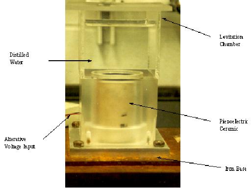
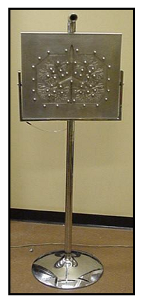
THE ACOUSTIC LEVITATOR
The acoustic levitator consists of a water chamber and a cylindrical piezoelectric ceramic. The levitator is fixed on a base of iron plate for acoustic isolation. The water chamber is constructed of transparent walls (Plexiglas) and measures 11 x 11 x 8 cm. A 2.0-in diameter cylindrical ceramic piezoelectric resides in the lower chamber. This transducer is capped with a circular glass driving plate 5 mm thick by means of a water resistant, electrically insulating epoxy. The inner and outside wall of the ceramic is line connected to receive voltage signal from the Generator. Applied with alternative current, a piezoelectric effect occurs as “vibration” due to the mechanical stress.
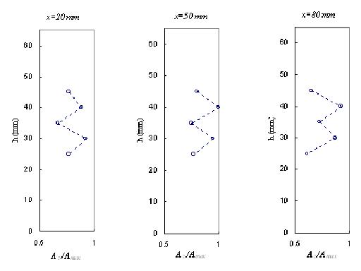
Fine adjustment of water depth and/or levitation frequency is used to create an acoustic standing wave. The levitation cell is able to produce one full wavelength of standing wave, that is, one axial pressure minimum in the intermediate level and two axial pressure maxima upper and lower along vertical axis. Therefore, smaller than resonance bubbles will be attracted towards pressure antipodes and larger bubbles are attracted to pressure nodes by the primary Bjerknes force. The standing wave has minimum pressure amplitude in the intermediate level. Figure above shows the pressure variation along vertical axis in 3 locations (x, y) of the horizontal plane.
MUSSL BREATHING MACHINE
For Full Description and Presentation of the Breathing Machine, click here
The MUSSL Breathing Machine consists of the following machined components:
– Casing
– Cam Supports
– Cams
– Beam and Slider
– Bellows Plate
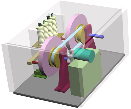
The weight and ceiling are made out of plexiglass.
There were 2 issues that had to be resolved here:
1) Difficulty in synchronizing 2 motors.
2) Severe sliding of outer beam along inner beam leads to bending of bellows.
The methods involved in breathing rate control were the Resistive Speed Control and the Pulse Width Motion (PWM) Speed Control and these are highlighted below.
RESISTIVE SPEED CONTROL
– R1 = motor, R2 = resistor
– Resistor reduces voltage delivered to motor
– Simple to implement
– Extreme inefficiency and possible danger
PULSE WIDTH MOTION (PWS)
– Splits voltage supply into pulses and controls the pulse width, hence the total voltage
– Each pulse carries full voltage & torque
INHALER TESTING SYSTEM
For Full Description and Presentation of the Inhaler Testing Machine, click here
This system is basically a lung model which is designed to provide direct flow visualization.
THE VACUUM CHAMBER
The vacuum chamber is two meters high and one meter in diameter. It is made of stainless steel. This chamber can tolerate pressures as low as Torr. The Intelvac Company of Canada manufactured the chamber in 5 months. The chamber is equipped with 36 view ports spread on its wall to allow observation and measurement of spray or droplets at various locations in the chamber. The chamber also has 32 one-inch feed-through holes with base plate flanges on the top and bottom plates, 12 QF-40 flanges on top and on the walls and 4 QF16 flanges on the top. The vacuum chamber is connected to an Edward vacuum pump package through an ISO 63 port and proper tubing and fittings. The Edward vacuum pump consists of a mechanical rotary vane pump, E2M40 and a booster pump EH240 for high vacuum applications.
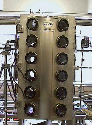
The pump package is by Kurt J. Lesker company, USA. To circulate cooling water and supply air, signals, thermocouples and electricity, appropriate types of feed-throughs were installed on the chamber. The chamber also has a hinged door to provide access to the inside of the chamber. It also has a convective pressure gauge, which is mounted horizontally on top of the chamber. The walls of the vacuum chamber are equipped with designated water traces to control the temperature of the chamber walls and consequently the ambient temperature within the chamber. Employing these well-distributed water channels, it is possible to reach to a uniform internal temperature. There are also several feed-throughs and the pressure gauge which are mounted on top of the chamber.
COMBUSTION CHAMBERS
MUSSL is equipped with several types of combustion chambers. Both gas and liquid burning combustion chambers are avaibale. The chambers are equipped with optical access and ports for flow diagnostics. The picture below is our setup for the flame spread investigations.
 DATA ACQUISITION SYSTEM
To measure temperature within the chamber, to trigger the camera, and to trigger the pulse generator, an IEEE 488 GPIB card, a temperature module, a non-conditioning module, a SCXI box to accommodate modules and the LabView software are used.
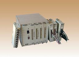
By using LabView software and writing appropriate virtual instruments, which are LabView programs, we will be able to manage experiments and send signals to or the computer to different components of the system.
SHOCK TUBE
PARALLEL PROCESSING
Three dimensional multi phase flow simulation is computationaly expensive and accurate simulation demands high computation power; as a result, parallel processing can be employed to solve computationally demanding problems.